小型可编程控制器外壳的4个角上,均有安装孔。有两种安装方法,一是用螺钉固定,不同的单元有不同的安装尺寸;另一种是DIN(德国共和标准)轨道固定。DIN轨道配套使用的安装夹板,左右各一对。在轨道上,先装好左右夹板,装上PLC,然后拧紧螺钉。为了使控制系统工作可*,通常把可编程控制器安装在有保护外壳的控制柜中,以防止灰尘、油污、水溅。为了保证可编程控制器在工作状态下其温度保持在规定环境温度范围内,安装机器应有足够的通风空间,基本单元和扩展单元之间要有30mm以上间隔。如果周围环境超过55C,要安装电风扇,强迫通风。
为了避免其他外围设备的电干扰,可编程控制器应尽可能远离高压电源线和高压设备,可编程控制器与高压设备和电源线之间应留出至少200mm的距离。
当可编程控制器垂直安装时,要严防导线头、铁屑等从通风窗掉入可编程控制器内部,造成印刷电路板短路,使其不能正常工作甚至损坏。
2.电源接线
PLC供电电源为50Hz、220V±10%的交流电。
FX系列可编程控制器有直流24V输出接线端。该接线端可为输入传感(如光电开关或接近开关)提供直流24V电源。
如果电源发生故障,中断时间少于10ms,PLC工作不受影响。若电源中断超过10ms或电源下降超过允许值,则PLC停止工作,所有的输出点均同时断开。当电源恢复时,若RUN输入接通,则操作自动进行。
对于电源线来的干扰,PLC本身具有足够的抵制能力。如果电源干扰特别严重,可以安装一个变比为1:1的隔离变压器,以减少设备与地之间的干扰。
3.接地
良好的接地是保证PLC可*工作的重要条件,可以避免偶然发生的电压冲击危害。接地线与机器的接地端相接,基本单元接地。如果要用扩展单元,其接地点应与基本单元的接地点接在一起。为了抑制加在电源及输入端、输出端的干扰,应给可编程控制器接上专用地线,接地点应与动力设备(如电机)的接地点分开。若达不到这种要求,也必须做到与其他设备公共接地,禁止与其他设备串联接地。接地点应尽可能*近PLC。
4.直流24V接线端
使用无源触点的输入器件时,PLC内部24V电源通过输入器件向输入端提供每点7mA的电流。
PLC上的24V接线端子,还可以向外部传感器(如接近开关或光电开关)提供电流。24V端子作传感器电源时,COM端子是直流24V地端。如果采用扩展船员,则应将基本单元和扩展单元的24V端连接起来。另外,任何外部电源不能接到这个端子。
如果发生过载现象,电压将自动跌落,该点输入对可编程控制器不起作用。
每种型号的PLC的输入点数量是有规定的。对每一个尚未使用的输入点,它不耗电,因此在这种情况下,24V电源端子向外供电流的能力可以增加。
FX系列PLC的空位端子,在任何情况下都不能使用。
5.输入接线
PLC一般接受行程开关、限位开关等输入的开关量信号。输入接线端子是PLC与外部传感器负载转换信号的端口。输入接线,一般指外部传感器与输入端口的接线。
输入器件可以是任何无源的触点或集电极开路的NPN管。输入器件接通时,输入端接通,输入线路闭合,同时输入指示的发光二极管亮。
输入端的一次电路与二次电路之间,采用光电耦合隔离。二次电路带RC滤波器,以防止由于输入触点抖动或从输入线路串入的电噪声引起PLC误动作。
若在输入触点电路串联二极管,在串联二极管上的电压应小于4V。若使用带发光二极管的舌簧开关,串联二极管的数目不能超过两只。
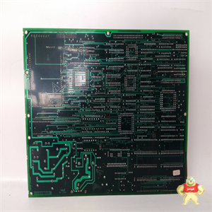
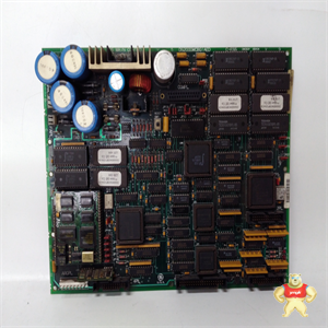
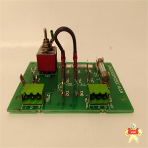
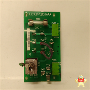
There are mounting holes on the four corners of the small programmable controller housing. There are two installation methods: one is to fix with screws, and different units have different installation dimensions; The other is DIN (German Republican standard) rail fixation. The DIN rail is equipped with a pair of mounting cleats, one on the left and one on the right. On the track, first install the left and right clamping plates, install the PLC, and then tighten the screws. In order to make the control system work smoothly, the programmable controller is usually installed in the control cabinet with protective shell to prevent dust, oil and water splashing. In order to ensure that the temperature of the programmable controller is kept within the specified ambient temperature range under the working state, the installation machine shall have sufficient ventilation space, and there shall be an interval of more than 30mm between the basic unit and the expansion unit. If the ambient temperature exceeds 55C, an electric fan shall be installed for forced ventilation.
In order to avoid the electrical interference of other peripheral equipment, the programmable controller shall be as far away from the high-voltage power line and high-voltage equipment as possible, and a distance of at least 200mm shall be reserved between the programmable controller and the high-voltage equipment and power line.
When the programmable controller is installed vertically, it is necessary to prevent the wire head, iron filings, etc. from falling into the programmable controller from the ventilation window, resulting in short circuit of the printed circuit board, making it unable to work normally or even permanently damaged.
2. power wiring
PLC power supply is 50Hz, 220V ± 10% AC.
FX series programmable controller has DC 24V output terminal. This terminal can provide 24V DC power for input sensing (such as photoelectric switch or proximity switch).
If the power supply fails and the interruption time is less than 10ms, the PLC will not be affected. If the power interruption exceeds 10ms or the power drop exceeds the allowable value, the PLC will stop working and all output points will be disconnected at the same time. When the power supply is restored, if the run input is connected, the operation will be carried out automatically.
For the interference from the power line, PLC itself has enough resistance. If the power interference is particularly serious, an isolation transformer with a transformation ratio of 1:1 can be installed to reduce the interference between the equipment and the ground.
3. grounding
Good grounding is an important condition to ensure the reliable operation of PLC, which can avoid the accidental voltage impact. The grounding wire is connected to the grounding terminal of the machine and the basic unit is grounded. If the expansion unit is to be used, its grounding point shall be connected with the grounding point of the basic unit. In order to suppress the interference added to the power supply, input terminal and output terminal, the programmable controller shall be connected with a special ground wire, and the grounding point shall be separated from the grounding point of power equipment (such as motor). If this requirement cannot be met, it must also be grounded in common with other equipment, and it is forbidden to be grounded in series with other equipment. The grounding point shall be as close to PLC as possible.
4. DC 24V terminal
When the input device with passive contact is used, the 24V power supply inside the PLC provides 7ma current at each point to the input terminal through the input device.
24V terminal block on PLC can also supply current to external sensors (such as proximity switch or photoelectric switch). When 24V terminal is used as sensor power supply, com terminal is DC 24V ground terminal. If the expansion crew is used, the 24V end of the basic unit and the expansion unit shall be connected. In addition, any external power supply cannot be connected to this terminal.
In case of overload, the voltage will drop automatically, and the input at this point has no effect on the programmable controller.
The number of input points for each type of PLC is specified. For each unused input point, it does not consume power, so in this case, the ability of 24V power supply terminal to supply current to the outside can be increased.
The empty terminals of FX series PLC cannot be used under any circumstances.
5. input wiring
PLC generally accepts the switching value signals input by travel switch, limit switch, etc. The input terminal block is the port for the load conversion signal between the PLC and the external sensor. Input wiring generally refers to the wiring between external sensor and input port.
The input device can be any passive contact or NPN tube with open collector. When the input device is connected, the input terminal is connected, the input line is closed, and the LED for input indication is on.
Photoelectric coupling isolation is adopted between the primary circuit and the secondary circuit at the input end. The secondary circuit is equipped with RC filter to prevent PLC malfunction caused by input contact jitter or electrical noise cascaded from the input line.
If diodes are connected in series in the input contact circuit, the voltage on the diodes in series shall be less than 4V. If reed switch with LED is used, the number of diodes in series shall not exceed two.

![]() 4年
4年


 There are mounting holes on the four corners of the small programmable controller housing. There are two installation methods: one is to fix with screws, and different units have different installation dimensions; The other is DIN (German Republican standard) rail fixation. The DIN rail is equipped with a pair of mounting cleats, one on the left and one on the right. On the track, first install the left and right clamping plates, install the PLC, and then tighten the screws. In order to make the control system work smoothly, the programmable controller is usually installed in the control cabinet with protective shell to prevent dust, oil and water splashing. In order to ensure that the temperature of the programmable controller is kept within the specified ambient temperature range under the working state, the installation machine shall have sufficient ventilation space, and there shall be an interval of more than 30mm between the basic unit and the expansion unit. If the ambient temperature exceeds 55C, an electric fan shall be installed for forced ventilation.